01
Problem
A train horn needs compressed air, and the compressor that makes it is a 12 V, 180 W motor — 15 A of continuous draw. That is several times what any accessory circuit in the car was wired for, and the compressor had to live in the trunk, about fifteen feet of wire away from the battery.
Fifteen amps over fifteen feet is enough distance for voltage drop to matter. A motor fed at a lower voltage than it was rated for turns more slowly, draws more current, and takes longer to fill the tank. So the question was not really which wire fits — it was how much voltage I was willing to give up between the battery and the trunk, and which conductor would hold me to it.
I worked the numbers before I bought wire.
02
Requirements & constraints
Everything downstream follows from these, so they are worth stating as numbers rather than intentions.
| Parameter | Value | Where it came from |
|---|---|---|
| Supply voltage, engine running | ~14.0 V | Alternator output, not resting battery voltage — later measured at 13.92 V |
| Target at the compressor | 12.6 V | Rated 12 V, with a little headroom |
| Total drop allowed | 1.4 V | The difference between the two above |
| Compressor current | 15 A | 180 W ÷ 12 V |
| Run length | 15 ft | Battery to trunk, positive side |
| Return path | ~0 Ω | Chassis ground at the frame, assumed negligible |
| Connection resistance | 50 mΩ | Assumed total across every joint in the run |
| Conductor temperature | 149 °F | Worst case, not room temperature |
| Horn solenoid | 4 Ω | Measured, not taken from a spec sheet |
Two of those are judgement calls rather than measurements: the 50 mΩ allowance for connections, and the decision to work at 149 °F instead of room temperature. Both make the answer more conservative, and the second one turns out to decide the whole thing. The one assumption I could check afterwards — the 14.0 V supply — came back within 80 mV.
03
Design
Spending the voltage budget
1.4 V is the entire allowance, and the wire does not get all of it. Every crimp, terminal, switch and fuse holder in the path has resistance too. Allowing 50 mΩ across all of them costs 0.75 V at 15 A, which leaves 0.65 V for the conductor itself.
The design budget, split between connection losses and the conductor, with what 12 AWG actually leaves unspent.
Turning 0.65 V into a wire gauge
The allowance converts to a resistance, the resistance to a per-thousand-foot rating, and the rating to a gauge from a table.
The first gauge that comes in under the limit wins. 14 AWG misses it by three percent.
| Gauge | Ω/1000 ft @ 77 °F | Ω/1000 ft @ 149 °F | Drop over 15 ft | Verdict |
|---|---|---|---|---|
| 16 AWG | 4.09 | 4.73 | 1.06 V | Fails |
| 14 AWG | 2.58 | 2.97 | 0.67 V | Fails at 149 °F |
| 12 AWG | 1.62 | 1.87 | 0.42 V | Selected |
| 10 AWG | 1.02 | 1.18 | 0.27 V | Passes, heavier than needed |
The temperature column is what decides this. At 77 °F, 14 AWG sits at 2.58 Ω/1000 ft and comes in under the ceiling comfortably. Hot — bundled against a trunk floor on an Alabama afternoon — it rises to 2.97 and fails. Choosing the worst-case column instead of the convenient one is the entire difference between 14 and 12 AWG here.
With 12 AWG installed, the conductor drops 0.42 V rather than the 0.65 V it was allowed. Predicted total loss is 1.17 V against a 1.4 V budget, putting roughly 12.83 V at the compressor — slightly better than the 12.6 V target, with 0.23 V of margin left over. What the meter said is in Verification.
The circuit
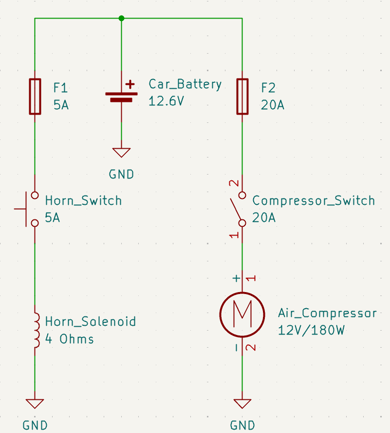
Two independent branches off the battery, each with its own fuse and its own dash control. The compressor branch is the 12 AWG run: battery terminal → 20 A fuse → manual 20 A switch under the dash → compressor. The switch sits in the high-current path, so it carries the full 15 A. The horn branch is 20 AWG left over from another job, through a 5 A fuse and a 5 A momentary button; the solenoid measured 4 Ω, so it draws a little over 3 A and the smaller wire is plenty.
Both fuses are there for short-circuit protection — a conductor chafing through to chassis — not overload protection for the motor. A 20 A fuse on a 15 A motor will let a stalled or failing compressor keep drawing well past its rating; what it will not do is let a dead short burn the run.
04
Build
As installed, the compressor positive leaves the battery terminal, passes through the 20 A fuse, runs forward to the manual 20 A switch under the dashboard, and continues back to the compressor in the trunk. The solenoid has its own 20 AWG run off the battery through the 5 A fuse and a 5 A momentary button on the same dash panel. Neither branch has a negative run; both return through the chassis.
Routing the compressor feed by way of the dash is the one thing the calculation did not account for — the switch is a detour, and the wire pays for it twice. The measurement in the next section says the budget absorbed it.
05
Verification
The predicted column is what the calculation says. The measured column is a multimeter at the battery and at the compressor terminals, engine running and the compressor under load.
| Parameter | Predicted | Measured | Method |
|---|---|---|---|
| Supply voltage, engine running | 14.0 V | 13.92 V | Meter at the battery, engine running |
| Voltage at the compressor, under load | 12.83 V | 12.68 V | Meter at the compressor terminals while running |
| Total loss, battery to compressor | 1.17 V | 1.24 V | Difference between the two readings above |
The budget held. 12.68 V arrives at the motor against a 12.6 V target, and the run loses 1.24 V against the 1.4 V allowed. The supply assumption held too — 13.92 V measured against the 14.0 V the budget was written around.
Two things are worth saying honestly about that result. First, the margin is thinner than the budget makes it look: because the alternator came in 0.08 V low, the real allowance to reach 12.6 V was 1.32 V, not 1.4 V. Spending 1.24 V of it leaves 0.08 V, not 0.16 V.
Second, the calculation was slightly optimistic — it predicted 1.17 V and the circuit lost 1.24 V, about 6 percent more. The conductor is the part I trust; the 50 mΩ connection allowance is the guess. With the wire near ambient when I metered it, 12 AWG accounts for roughly 0.36 V of the 1.24 V, which puts about 0.88 V — near 59 mΩ — across the joints, switch and fuse holders. That is the term I underestimated, and it is also the only one I can still improve without pulling new wire.
Working the same numbers hot is what makes the gauge decision worth the paragraph it got. Heat-soaked, the conductor adds roughly 0.06 V, taking the run to about 1.30 V — still inside the 1.32 V available. Had I taken 14 AWG off the room-temperature table, the same connections would have put the motor near 12.4 V and missed the target outright.
06
What I’d do differently
Put a relay near the battery
As built, all 15 A leaves the battery, travels up to the manual switch under the dash, and comes back to the trunk. A relay mounted at the battery would let a small dash switch drive the coil while the contacts carry the load, which does three things at once: it shortens the heavy run, it takes the switch contacts out of the 15 A path, and it removes several of the joints that turned out to be the largest single term in the measured 1.24 V. This is the change I would make first, and it is the one most engineers would ask about.
Meter the conductor on its own
The 1.24 V I measured is the whole path — wire, terminations, switch and fuse holder together. A reading taken directly across the two ends of the 12 AWG would split that into conductor and connections instead of leaving the division to an estimate, and it would also settle the run length. The calculation assumes 15 ft, but the positive goes battery → dash → trunk, so the installed length is almost certainly longer; as it stands, extra length and extra connection resistance are indistinguishable inside that one number.
Size the fuse against inrush, not running current
The 20 A fuse was chosen against 15 A of steady draw. A DC motor pulls several times its running current in the first fraction of a second, and more when it starts against a partly-full tank, so the element type matters as much as the rating — a slow-blow element rides through the surge where a fast-acting one may not. I would specify that deliberately rather than let it be whatever the fuse drawer had.
Check ampacity explicitly
The gauge was chosen on voltage drop alone. 12 AWG carries 15 A with comfortable margin in chassis wiring, so drop almost certainly governed — but that is worth confirming against an ampacity table and stating, rather than assuming. Drop governed; ampacity had margin.
Conductor resistance figures from The Engineering ToolBox, Copper Wire — Electrical Resistance vs. Gauge. Schematic drawn in KiCad. Calculations and measurements dated February 2025.